5 Essential Tools to Master in Artec Studio Software
For all the glory that the Artec 3D portable scanners receive, we can’t forget that Artec Studio 3D scanning software is the “secret sauce” that makes the whole process work so well. Built to take your 3D scanning projects from scan to polygon-model-export, Artec Studio contains a simple and intuitive core workflow, as well as myriad branches of processing tools and elements that help you handle all of your unique and interesting scanning projects.
Mastery of these tools takes an accumulation of experience, and with that comes knowledge of pitfalls, so a little bit of determination early on can pay dividends twice as fast. Whether you’re new to the world of 3D scanning or have successfully created multiple models, it never hurts to refresh your skills. Here are five essential Artec Studio tools that will make your life significantly easier when processing a scan.
1. Global Registration
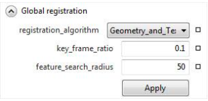
By far, the most important data processing tool for maximizing overall quality is the global registration. Found within the Tools ribbon, global registration is usually one of the last steps in any given project, but its importance deserves first mention. Global registration is essentially a pattern recognition algorithm that fits all of the frames of data within a project together as best as possible. To help you do this, global registration gives you three primary options to adjust.
Global Registration Options
Algorithm
The first is the algorithm: geometry only, or geometry + texture. All Artec 3D scanners except for the EVA Lite collect data in two layers: geometry (shape) and texture (color). If your object has a color pattern to it, such as wood grain, text, or even freckles, the geometry + texture algorithm is the one to use.
Key Frame Ratio
The second option to consider is the key frame ratio. Think of this as the “strength’ of the algorithm, with 0.1 being considered low strength and 0.6 being considered high strength, with 1 being the maximum. You generally want to keep key frame ratio as low as possible for the sake of speed, but it is sometimes necessary to raise the key frame ratio to higher levels if the data still doesn’t fit properly with a low ratio.
Feature Search Radius
The final option to consider is the one least used: feature search radius. It’s usually best to keep this at the default value, because it controls how far away the algorithm considers aligning data. You should lower this if you are 3D scanning an object with thin, repetitive features, so that frames are limited in how far they can move.
Using Global Registration During 3D Scanning
An important thing to note about global registration is that it is sometimes most effective to use it first in your processing workflow, running global registrations on the individual scans before aligning them all together. If you scan a part sitting on a turntable or base that has a rich geometry or color pattern to it, and you intend to scan multiple times in multiple positions (top, bottom, side, etc.), don’t automatically delete this base right away! When you do this, you maximize the chance your project is a success on the first try.
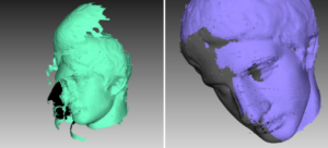
Overall, this tool is so important because while you are 3D scanning, frames of data are aligned together in sequence, almost like a game of telephone. This can cause frames of data to sometimes fit imprecisely, resulting in multiple layers of data in the same spot—an error also known as an “onion skin.” As with cooking, you never want onion skins in your final product! Global registration eliminates onion skins and properly registers the data together, enabling a clean and beautiful final model.
2. Align
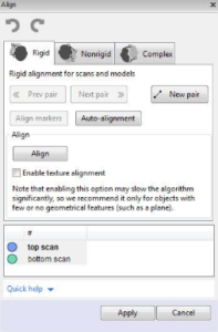
Found in the ribbon as its own button, the align tool is the most critical step for any project that has been scanned in multiple positions. Despite being ranked number one on our list of tools, not even the mighty global registration can fix scans that are fundamentally in different positions in 3D space! After you scan an object and erase unnecessary data like the table and background, and also after any optional global registrations on the individual scans, you will want to align them together.
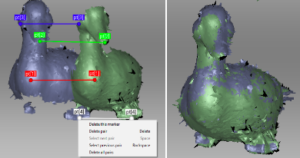
When aligning data, first consider how much overlap data you have. A good way to think about this is to think about a 3-legged stool. If the legs are all in a narrow line, the stool will be unstable. If the legs are wide and spread apart, the stool will be stable. To figure out which scans to align together first, identify the scans that have the most amount of overlap, such that clicking three points of commonality, like three legs on a stool, would be very stable.
The align tool feels different from the other workflow tools because instead of subtracting or adding data, you are simply transforming it in 3D space, so it requires a different skillset. This tool relies heavily on your ability to navigate the 3D workspace via pan/rotate/zoom and click points of commonality, so keyboard and mouse control are very important to maximizing quality and minimizing 3D scanning time.
Using Align
- First, Artec Studio will prompt you to select one scan that is locked (registered, denoted by a blue dot) and one scan that is moving (unregistered, denoted by a green dot). You’ll ideally click three or more points of commonality between them, and the software will figure out how to fit the scans together based on your inputs.
- After choosing two or more scans to align together, you’ll see both on the screen in different positions. Hold the shift key down so that when you pan/rotate/zoom, it only moves the unregistered scan. For ease of use, first rotate the registered scan to be in a usable position, then select the unregistered scan.
- Hold shift and pan the unregistered scan to the side, then double click inside to create a pink dot: the new rotation center.
- When you hold shift to rotate the unregistered scan, it will rotate it about the pink dot rotation center, making it much easier to position the registered and unregistered scans in the same orientation, side by side.
Navigating the 3D Scanning Process
Don’t forget to consider if any scans are already pre-aligned. You can select multiple scans as registered, and multiple scans as unregistered to make groups of scans behave as one, and you will likely want to do this if you notice missing areas and decide to collect additional scans after aligning everything previously.
When scanning inanimate objects, you should strive to process your data well, so that the rigid alignment tab is the only one you ever need to use. But if you scan a living being that moves and breathes and doesn’t stand perfectly still, or if you scan something that moves on its own during scanning, you may want to use the non rigid alignment tab.
The nonrigid alignment tab will literally deform the unregistered scan to match the general position of the unregistered one. An example of when you may need to use this is a body scan of someone who accidentally turns their head. The catch to this tool is that it only works on models/fusions, and not on the raw scans, so you need to run fusion on the different movement positions first to make this work.
3. Fusion
Technically, this one is three different tools at once, but only because they’re all listed separately in the tools ribbon! Fusion constructs a new 3D model from all the raw scan data. Raw scan data is essentially a 3D mosaic of hundreds, if not thousands, of frames of 3D data. All this XYZ point data needs to be combined—but more than this, the 3D scanning software needs to determine the resolution of the resulting model.
Resolution in 3D Scanning
Resolution is a measure of point spacing (in Artec Studio software, this is always listed in millimeters), so a resolution of 0.1 means 0.1 mm spacing between datapoints—a very high detail resolution!). Unlike with TVs, where the main metric for resolution is in pixels (the higher, the more detailed), resolution in the 3D scanning world is more like golf, where the lower the number, the better. If you have an object with sharp features, like an arrowhead, you will want to run fusion at the lowest supported value—for example, 0.1 for the Artec Space Spider or 0.5 for the Artec EVA and Leo.
Fusion will reveal many mistakes you may have made with data processing up until this point. Consider an example where you forget to run global registration, so your scan of a large object contains some onion skin defects. When running fusion at a high resolution, these onion skin layers will no longer look like harmless XYZ points in raw data, but will show up as ugly, oppressive, and ultimately nonviable polygons in your final model. Onion skins are always best fixed by using the global registration and align tools more effectively, but in the cases where it’s either unimportant or not possible to do so, then you can still get usable data simply by lowering the resolution.
Consider the earlier example where onion skins look quite bad when running fusion at 0.1 mm. If instead you run fusion at 2 mm, then you experience the double-edged sword of a model that is both low resolution, but also free of double-layer defects.
Fusion Modes
There are three fusion modes to consider using in your 3D scanning project.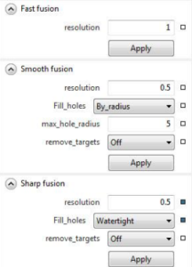
Fast Fusion
Fast fusion, as the name suggests, creates a 3D model as quickly as possible, but this mode lacks important options that other fusion modes contain. This mode is not used often, but it can be helpful as a sort of preview model to check your 3D scanning work before investing more time in the model. If you have an important client or frantic customer who needs to leave for the airport in 5 minutes and wants to preview the scan data before leaving, consider running fast fusion.
Smooth Fusion
Smooth fusion is the algorithm designed for 3D scans that have undergone movement, such as a human body scan, because it smooths the data as the fusion algorithm is run. This mode can make some very clean looking models! As the name suggests, smooth fusion will not give you a model with sharp features—so it’s best to use this mode when the fine details aren’t needed.
Sharp Fusion
Lastly, we have sharp fusion. This mode is designed to prioritize sharp corners, features, and details. Sharp fusion is the most common mode used when scanning inanimate objects, parts, and more.
Filling Holes in 3D Scans
Sharp fusion and smooth fusion both have special hole filling options that fast fusion does not. (A hole is a void or gap in the data, usually resulting from missing raw scan data in an area.) A commonly missed spot when scanning human bodies underneath the chin, so this is a common spot to need to hole fill for a 3D printed figurine. Using these hole filling options, you can either automatically fill all holes, resulting in a watertight mesh, or you can set a hole radius threshold to fill. If you set the hole fill radius to 5, for example, all holes with a radius of 5 mm or less will be filled, and all larger holes will be ignored. This is important for prototyping, as 3D printers need a watertight/hole-filled mesh to work properly.
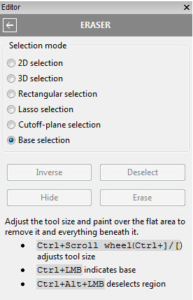
4. Eraser Tool—With Special Guest 3D Toolbar
The eraser tool in Artec is extremely powerful, containing both traditional eraser modes like brush, lasso, and rectangular selection, as well as smart modes like cutoff plane and base selection. To truly get the most out of the eraser tool, you need to combine it with its frequent partner-in-crime: the 3D toolbar. The 3D toolbar is in the top right of the main 3D view, to the lower-right corner of the Navigation Cube.
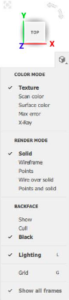
Artec Studio’s 3D Toolbar
The 3D toolbar, once clicked, brings up a quick menu showing the various ways you can render your data. For example, you can turn color on or off—which is helpful because color 3D data can oftentimes give the illusion of detail. Setting the render mode as points will show the XYZ data as actual data points, whereas render solid will show the raw scan as a fragmented solid shape that can be much easier to work with than points, mainly because a solid surface is easier to view and click on (especially useful to render as solid when using the Align tool).
Using the Eraser Tool and 3D Toolbar Together
So, how are these two tools connected? Using the eraser tool means you are selecting data to delete, so changing the display mode to points can more clearly show the exact data points you need to select and delete, compared to rendering as solid, which can obscure some finer details of the raw scan. It is common to frequently toggle between solid and points render mode when processing data in order to reveal areas you need to delete, as well as keep track of onion skin defects that are easier to see when rendered in points mode or X-Ray mode.
Erasing Unnecessary Data in a 3D Scan
The base selection and cutoff plane selections are very similar in that they are designed to “draw a line” to delete data below. As the name suggests, the cutoff plane chooses a perfectly flat plane, and all XYZ points below the plane are deleted. If you scan a part on an undulating surface like carpet, the cutoff plan can sometimes delete everything except the peaks of the undulating surface and result in many small islands of data you would rather have deleted.
The base selection option was designed to deliver the expected benefits of the cutoff plane selection, where you simply select a small area and the software erases everything, even the undulations of the surface. If you scan an object on a turntable, and the turntable surface isn’t perfectly flat, the base selection tool is the one to use!
5. Undo and Redo
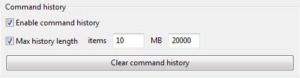
Sneaking in at number five, we have the undo and redo tools. You’ve definitely heard these terms outside of Artec Studio—they’re common PC commands. Developing the muscle memory to quickly undo with CTRL+Z and redo with CTRL+Y is key to utilizing one of the best features of Artec Studio: the extensive history. Much like Adobe Photoshop, Artec Studio 3D scanning software will create a history of commands and data manipulation, so that at nearly any time, you can undo the previous command. By default, the undo history is set to 10 commands, and this can be adjusted in the settings menu in the performance tab.
The reality of 3D data processing is that sometimes you will run a Global Registration or a Fusion or an Outliers Removal and have only the best guess as to what the result will be. Sometimes, running a command like fusion can reveal a problem not only with the global registration, but also the alignment! In these cases, being able to instantly undo two, three, or four steps is so much better than the alternative: creating new save files at every checkpoint.
Using other 3D scan data processing programs that only give you a single undo command feels prehistoric compared to Artec Studio’s default of 10. As is often the case, mastery of anything requires experience, practice, and trial and error. There is no better way to support this in 3D scanning software than with instant undo and redo options!
Make the Most of Artec Studio 3D Scanning Software
Artec Studio software is packed with dozens of tools and features, and the reality is that most projects only require a handful of tools to be successful. These five tools and features are the most common ones used to ensure a successful project—but that doesn’t mean that you need to limit yourself to only using them. 3D scanning is a rapidly expanding field, and there’s always more to be learned!
Artec Eva and Artec Leo 3D Scanners Receive High Definition (HD) Upgrade
As the progress of technology marches on, consumers will rightfully wonder more and more whether their purchase of some product today will become obsolete by tomorrow. Although cell phones and PC operating systems have conditioned us to assume the availability of software updates after purchase, very few of us expect massive overhauls, much less anything more than marginal new features.
Artec 3D shocked the world by announcing a collection of new features summed up as: Artec HD Mode! Available for free to all users of Artec Studio 15 (and anyone who is currently on an annual software license), Artec HD Mode upgrades existing Artec Leo and Artec Eva 3D scanners with new features that effectively advance them a generation ahead in 3D scanning power.
Developing Artec’s HD 3D Scanning Mode
Powering the new Artec HD mode is a first-of-its-kind neural network developed by Artec 3D’s Artificial Intelligence (AI) experts. The Artec AI engine was trained on hundreds of thousands of projects to detect familiar features and shapes in order to accurately reconstruct 3D scanned surfaces with higher resolution than was previously possible. The net result of all this work is the ability for a user to select an upscaling amount, from 2x up to 64x, which results in higher quality raw data before any registrations or fusions are performed!
The Next Tier of 3D Scanning Power
The HD Mode upscaling process has several special benefits other than increased resolution. As a result of the upscaling process, noise and other defects will be dramatically lowered, and what used to require hole-filling is now being properly reconstructed from the raw 3D scan data.
Below is a table highlighting some of the chief quality of life improvements offered by HD Mode 3D scanning:
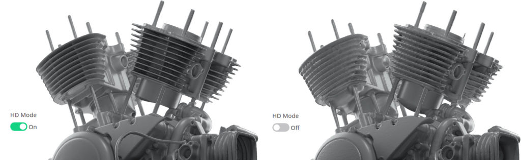
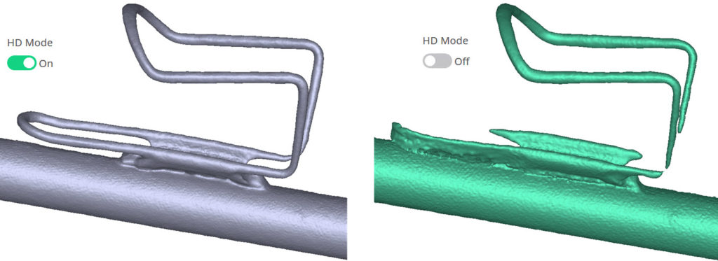
 | Sharper Features on Smaller Elements The most obvious improvement is the sharper feature resolution. Consider a bicycle gear: when 3D scanned with the Leo in normal mode (green) the gear teeth appear rounded, however in HD mode (blue) the gear teeth are appropriately sharp and high quality. With sharper definition comes the ability to detect smaller and thinner features that might otherwise require an Artec Space Spider to capture. |
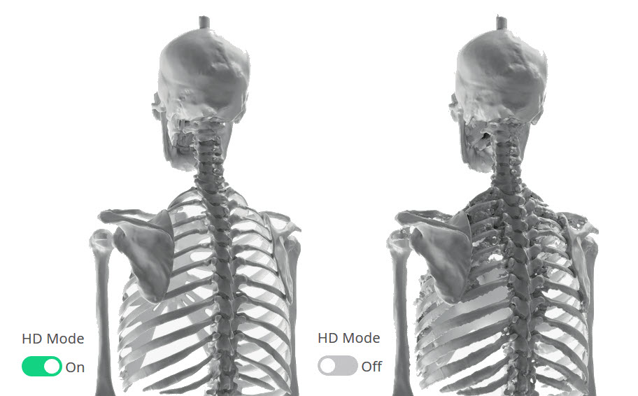 | Clean Data in Hard to Reach Spots HD Mode 3D scanning’s greatest benefit to some users will be the massively improved clean data. Consider 3D scanning the skeleton in the image. The complex occlusions and undercuts in the ribcage means that normal 3D scan data will oftentimes create clusters of noise that can be difficult to filter out. With HD Mode on, this false noise is removed without requiring the Outliers Removal tool or manual erasing. |
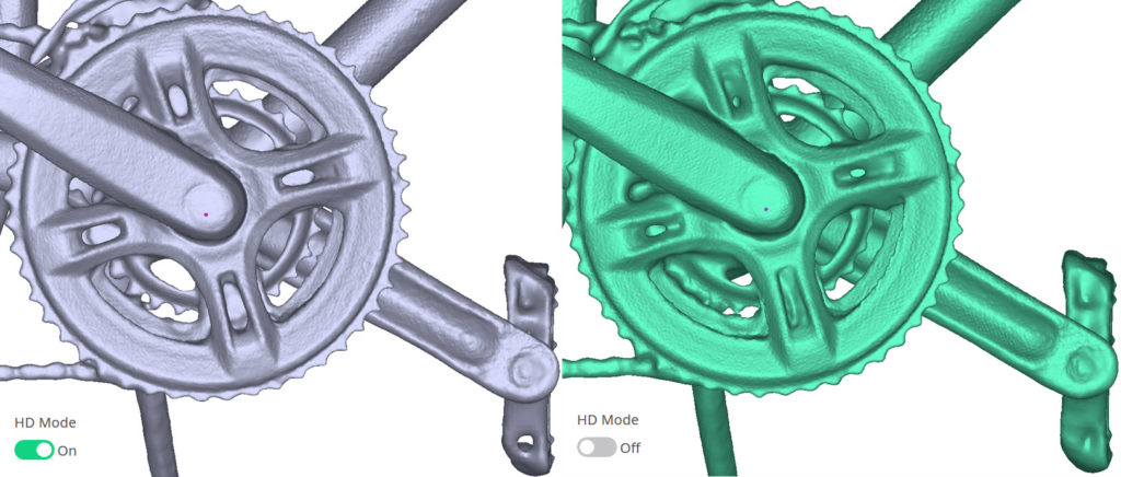
 | Fewer Holes, Less Chunky Data on Shiny Surfaces With upscaled data comes higher confidence in the meshing of small features, especially on dark and shiny surfaces. Consider the water bottle cage on the bicycle in the image, and how there are several spots of added material due to noise, and missing material due to lack of confidence in the data. HD Mode completely fixes these issues. |
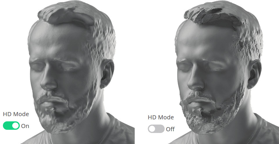 | Hair, Fur, and Other Fine Surfaces HD Mode also works on hair! Previously, 3D scans of hair would at best look like marble busts where hair was smooth and chunky. HD Mode 3D scanning now adds an element of sharpness and crispness to hair and requires less hole filling in order to capture a high quality mesh. Fur and other fine surface conditions also benefit from HD Mode. |
Things to Consider:
HD Scanning Mode is now available for the Artec Leo and Artec Eva 3D scanners however, the amount of raw data generated is massively increased. For example, a single frame of data from the Eva contains about 64,000 polygons, whereas HD mode can go all the way up to ~3 million polygons per frame. With this increased raw data, several important PC related items need to be considered:
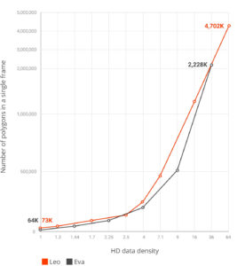
HD Data Density (Source: Artec 3D)
- Larger File Size will be needed to save a project
- More RAM will be needed to manage processing the raw data
- More powerful specs including processor and graphics card will be needed to manage all this data
As a result, HD Mode 3D scanning should not be performed on tablet PCs that otherwise work well when processing Eva data. When bringing the Eva to a project requiring HD 3D scanning, please be sure to bring a high-performance laptop to be able to complete the HD upscaling process as quickly as possible.
The Artec Leo performs HD reconstruction once data is imported into Artec Studio, not immediately after 3D scanning as is the case with the Eva. This allows you to safely capture data with the Leo in HD Mode while on a project site without the need to wait for the HD upscaling process.
As with most 3D scanning related features, practice makes perfect. HD Mode allows you to choose the level of HD upscaling, so you can practice on smaller projects with lower upscaling first. Artec is well known for continuously updating new and old software features so you can expect future improvements to HD mode in the months and years ahead.
At Laser Design, a brand of CyberOptics Corporation, we pride ourselves on our expertise in the field of 3D scanning, and especially our knowledge of using the Artec 3D scanners. Over the years, we’ve seen our fair share of 3D scanning successes and blunders alike. We’ve provided scanning solutions to thousands of customers, and we’re here to support when you need 3D scanning resources. Contact us today to learn more about our 3D scanners and industrial scanning services.
Happy scanning!