MOTION TRANSPORT RETROFITTING
Interfacing an LDI Laser Probe to a Motion System
Other Relevant Documents
- MCSDK.chm which is a motion control driver development guide.
- CMM or CNC Retrofit Flow, which is a flow chart describing the process of retrofitting a motion transport system with a laser probe.
- CMM Retrofit Form, which is a questionnaire to be filled out prior to configuring the retrofit kit.
General
The laser probes collect dimensional data in their own reference frame, and in their own field of view which is typically small compared to the objects being digitized. For these reasons, the probes are usually connected to some kind of motion control system, to move the probe over the part, or the part under the probe, and the two reference frames must be coordinated. This document discusses the interfacing issues when attaching an LDI laser probe to a motiontransport, such as a CMM or CNC.
There are at least two degrees of integration when connecting the probe to a motion control system. This is because the laser probe, unlike typical touch probes, does not need to be in an exact location to measure because of its relatively large field of view (fov). It just needs to know exactly where it was when data was collected so that the scan data can be accurately positioned in space. This is because of the large field of view and high data collection speed. With a depth of field ranging between about an inch, and up to several, and the ability to collect at a rate of thousands of points per second, all that matters is that the probe passes through the vicinity of interest on the part. At one level of integration, there is a loose coupling between the probe and motion system where the probe is passively collecting data from whatever surfaces come within its field of view, and the encoders are monitored and latched simultaneously with the scanning. At the next level, the probe is tightly coupled with motion and both are guided by the SSC software, even to the point of actively guiding by feedback from the probe to keep the part surface in its field of view. (SSC is the Surveyor Scan Control software which controls data collection by the probe.) The distinctions between the two approaches centers on where movesare initiated, how they are communicated, and how reference frames are combined to find the composite. The two modes are 1) SSC Passive Listening Mode, and 2) SSC Guided Movement. Each mode uses the same scheme for position monitoring, machine compensation, and probe alignment.
Position Monitoring
The scanning probe must be tightly coupled to machine position. To accomplish this, The Encoder Interface Unit (EIU), a secondary encoder reader, is integrated into the probe electronics. Other schemes are possible as long as they comply with the position feedback requirements specified in the Appendix below. But in the standard approach, the EIU offers very tight control of position, nearly jitter free. The EIU does not support machine compensation directly however. If the motion system being retrofitted uses error mapping, and can support the monitoring requirements with compensated position information that is most desirable. (See Position Interface Requirements in the Appendix below.) However, a driver would need to be written tocommunicate with the motion transport controller to pick up position information. Alternatively, compensation tables could be developed in SSC. See Error Mapping below.
Error Mapping
Some motion transports are so accurate that the error contribution relative to the probe is small and can be ignored. However, a common approach to machine design is simply to ensure that they are repeatable, and then map them to compensate the encoder readings to correct them. If the machine being retrofitted falls into this category, it must be addressed. To date, we have run across two levels of compensation: strictly volumetric, and volumetric with orientation. In strict volumetric compensation, a corrected x,y,z is created for each encoder reading in the range of the motion system. If the machine has this type of table, a translation needs to be done, to convert the native comp table to SSC format. (See Appendix for Native LDI Comp Table format definition.) The volumetric approach is partially effective, removing linearity and squarness errors, but for straightness errors, angle compensation is also required. For this, direct SSC access to the tables is required. This can be accomplished by making the comp tables accessible to SSC, via a function call where encoder position and offset are passed with the function, and corrected position is returned. This needs to be done on the fly as opposed to precomputed since the combination of all possible offsets and positions to too large to store.
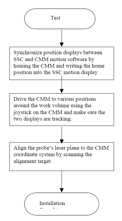
Probe Alignment
The probe can be mounted to the motion transport in any arbitrary orientation. Once mounted, the orientation relative to the motion transport must be determined. From then on, SSC can develop coordinates on the part surface by combining probe reference frame coordinates with motion transport coordinates. To measure the relative orientation between the probe and transport, SSC uses an alignment utility that calls for the probe to be moved about a sphere, to derive the transformation. This can be done with either a singular sphere, or an array of spheres. If a single sphere is used, the sphere must be moved through the field of view in a regular pattern of 3 x 3 or 4 x 4. With no control of probe motion by SSC, as in the case of the Passive Listening Mode integration level, the moves need to be mimicked. If the transport is manually driven, this is supported with prompts from SSC, directing the operator where to move the probe. If the transport is motor driven, and programmable, the alignment sequence can be set up, and stored,then called up by the operator as needed. (See SSC User Manual for a description of the moves needed to align the probe to the transport and the algorithm used to determine the sequence of moves, regardless of probe orientation.) Alternatively, the sphere array can be mounted on the transport, aligned with it, then scanned in a single pass. The array is much faster, once it is aligned. So the trade off is usually dependent on whether the array can be left on the transport. The single sphere requires no alignment, and thus can be removed, and quickly replaced when needed. The size of the sphere array varies depending on the probe being used. See data sheets
for dimensions.
Level I: SSC Passive Listening Mode
This is the most straightforward way to retrofit a motion system with a laser probe. The probe is attached to the motion system and controlled by a computer that is completely independent of the control mechanism for the motion system. The only electrical interface is the encoder information that is monitored via secondary encoder reading electronics that is part of the probe electronics package. Scanning is accomplished when the operator simultaneously initiates motion and data collection. The SSC software controlling the probe monitors position. When the encoder signals, which are streaming in to the probe computer and electronics, begin to reflect motion, probe data is stored. When there is no motion, data is not collected. Additionally, the operator can use a collection button located on the key switch box or it can be rigged to be remote, which is ANDed with the motion. In either collection mode, the operator would observe the data being displayed on the SSC screen, plan and execute the next move, collect, and iterate until the desired coverage is achieved switching attention between the SSC display and the motion system. Joy stick control of the motion system is a very effective and intuitive way to collect the data in this mode. This is quite a satisfactory operating mode for applications that tend to do mostly one-time inspections.
Level II: SSC Guided Movement
At this level of integration, there is a communication link between the motion controller and the computer running SSC. (See the Surveyor Motion Control Developers Kit for details on how to write a driver for direct motion control from SSC.) This allows move trajectories to be sent to the motion controller directly from SSC, and even modified on the fly to track surfaces. On new parts that do not have scan paths pre-programmed, the operator can set up moves in the SSC screens. These are series of start and stop moves, which can be strung together to track complex contours where Z moves might be required to keep the part surface in the field of view. This mode of operation allows moves, and the probe data collection during the moves, to be seen in the same display which makes the operator’s job conceptually less complex, allowing visualization of what to do next: fill in gaps, move to the next area of interest, etc. And it makes the probe alignment easier since the SSC alignment utility can be used which is completely automated. Also, if the application involves repetition, this mode allows for entire part inspection sequences to be stored, recalled, and repeated, by SSC. A driver would have to be developed to communicate with the controller if one does not already exist. See Motion Requirements in theAppendix below.
Appendix I
CMM Retrofit Form
General CMM questions
- Make of CMM?
- Model?
- Year manufactured or refurbished?
- Current support organization?
- Controller manufacturer?
- Controller model?
- CMM accuracy?
- Is the CMM compensated for errors?
- Can a utility program be written that would accept nominal coordinates and return corrected coordinates?
- Has such a correction utility been written?
- Will other probes be used besides the laser probe after the retrofit?
Computer Placement
Where can the laser scanning computer be placed? (Needs to be positioned so operator can see the machine, and be close to the motion control station since they will be going back and forth between the two. Also, needs to be electrically connected to the probe, and to the encoder breakout box.)
Encoder Interface
- Where can we access the encoder signals?
- What type of scales are on the CMM currently?
- Signal types? (Prefer RS-422, differential, quadrature.)
- Connector type and pin-outs?
- Where can the EIU be placed? (Break the connection between the encoders and the controller, and place the EIU in series in this circuit. The box is approximately 10” x 7” x 8”.)
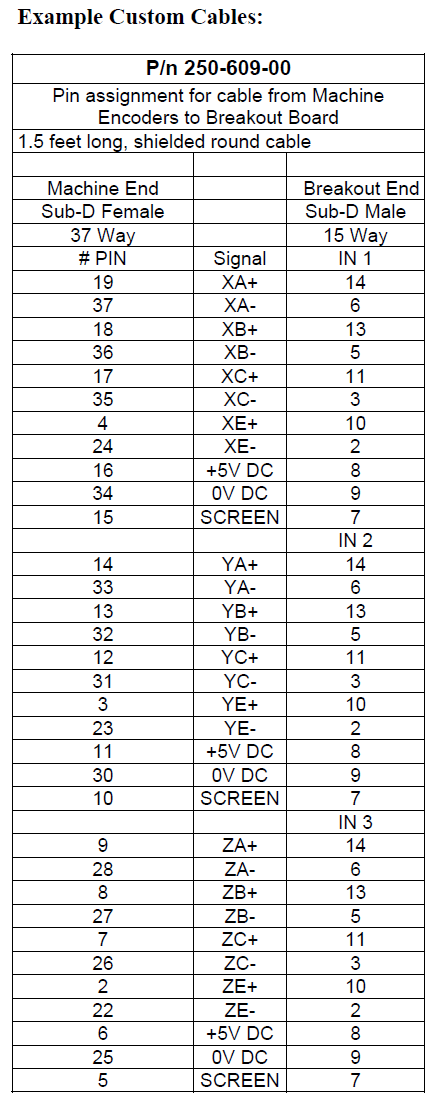
- How long will the encoder cables need to be? (The cables going between the encoders and the breakout box.)
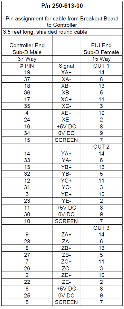
- How long will the controller cables need to be? (The cables going from the breakout box to the CMM controller.)
- How long will the computer cables need to be? (The cables going from the breakout box to the computer.)
- Encoder pitch?
- CMM move speed?
- CMM configuration? (Bridge, gantry, etc.?)
Probe Connection
- Will the manual indexer be used?
- How will the probe cable be routed? (Cable from the probe to the computer.
- How long will the cable need to be?
- Any special connection considerations? (We have a Renishaw adapter.)
- Best way to counterbalance? (If there is an air counter balance, can a regulator be added that the operator can adjust when he/she switches between the laser and lighter probes?)
- Cable strain relief mechanism? How will the end of the long run cable from the computer to the probe be fastened? (The probe has short pig tail cable that disconnects from the long run when it is removed. The pig tail cable can be any length, and it can be curled so as to be self retracting to keep out of the way.)
- Type of environment? (Temperature swings, dust, humidity?)
- Is there a location where we can repeatably mount an alignment target or leave one in place? (The alignment targets vary in size depending on the probe being used.)
Appendix II
CMM or CNC Retrofit Flow
Note that the assumption in Retrofit applications as opposed to Integrated systems is that on the latter, there is direct motion control from the SSC software. On Retrofits, motion is controlled from the native motion controller and software that were on the machine when LDI began the installation.
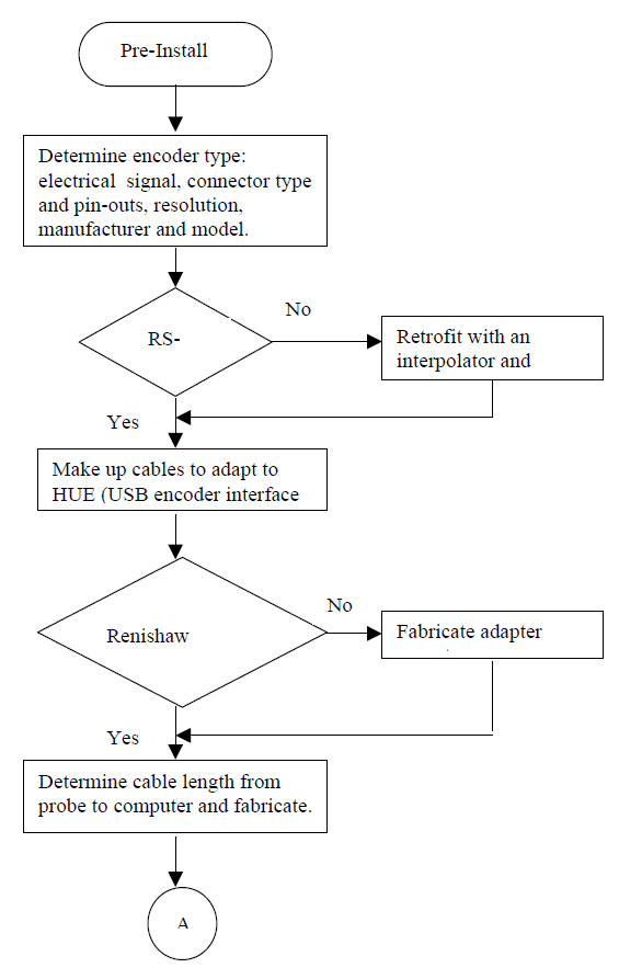
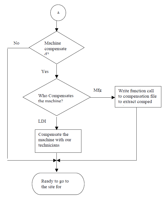
Note on compensation: The way we prefer to compensate the CMM’s is to use the comp tables developed by the manufacturer of the controller. We do not need to know anything about how it works, we only need to be able to call a function provided by the manufacturer, and supply the uncompensated positions, and get the compensated positions returned from the call. The alternative is to comp the machine ourselves. The problem with this approach is that every time the machine needs to be compensated again, it needs to be done twice.
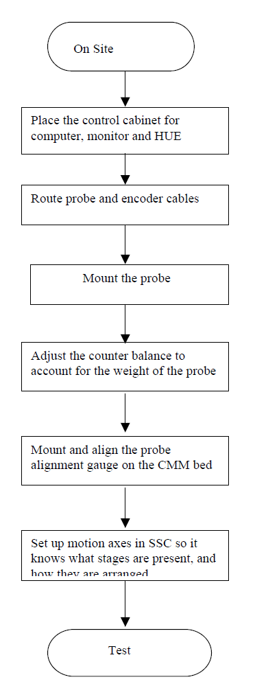
Note on Site Installation: If the installation is on a machine that we have not retrofitted before, it is best accomplished with the accompaniment of the organization that services the CMM, or someone that is familiar with the controller and a method of counterbalancing the Z axis, and routing of cables.
Appendix III
Position Interface Requirements
The VP board (Video Processing board for the RPS family of probes) generates a 125usec wide trigger pulse at a rate of 60Hz, to indicate that the probe took a scan. Position information must be latched at each trigger pulse to be sent back to SSC to be combined with probe data. The uncertainty in time between the trigger pulse and latching should result in no more than 10% of the system accuracy. For example, an RPS 150 probe, with .00035″ accuracy, moving at a rate of 2ips, the delay should be no more than .00035″ x 10% / 2ips = 17.5uS. If the uncertainty is greater than 17.5uS, the move rate can be slowed down to compensate. Additionally, as mentioned, the pulses arrive at a rate of once per 1/60th of a second. The device latching data and passing it to the computer running SSC must be able to keep up. The encoder positions can be buffered and sent in a packet as long as care is taken not to drop any, and keep them in order. The trigger pulse is a single ended, active high, TTL level signal.
Secondary Encoder Reader
There are two types of Encoder readers offered currently, the Sensoray board, and the USB interface (USB option available in Q3 of 2002).
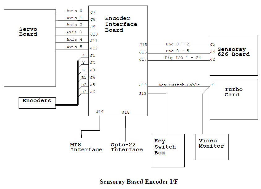
Sensoray based:
The Dynamic Scanning upgrade kit includes secondary encoder reading electronics that allows for tapping into the encoder lines on the motion transport to monitor position. In this way, at a minimum level integration, no communication, other than the wire connection to the encoders is required. The reader is placed in the middle, between the motion system encoders and the encoder reading device on the motion transport. The encoder cables are connected to the Encoder Interface Board (see diagram below), which buffers the signals with RS-422 transceivers, so the encoders only see one load. The signals are then passed on to the motion transport controller and to the secondary encoder interface board, residing on the PCI bus of the computer running SSC. When the probe collects a snap shot, the trigger pulse goes to the secondary encoder interface board, which latches the counters and generates an interrupt. SSC reads position and combines it with the data from the probe. The differential receivers are AM26LS33’s with 10K pull ups on + inputs and 10K pull downs on – inputs. The breakout board and 626 encoder reader are set up for quadrature encoder signals only.
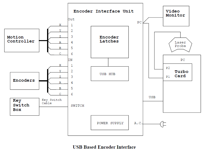
USB Based Solution:
The USB solution is the same as the Sensory solution in every way, except that the encoder latching electronics are packaged with the Breakout Board, in a package called the Encoder Interface Unit. This is a sand alone box, with it’s own power supply and a USB interface to the PC. Rather than interrupts over the PCI bus, a polling driver is running under Windows. The urgency to read data from the encoder latching is lowered in this solution since there is a built in FIFO on the encoder reader electronics.
Connector Descriptions
A.C. Power Input : 120/230 VAC 60 / 50 Hz 1 Ph 021 / 0 11 A
USB: USB 1.2, 12Mbit rate
PC: DB-9, Male for laser probe power and trigger pulse to encoder latches.
Switch: DB-9 female to Key Switch Box to turn the probe on or off
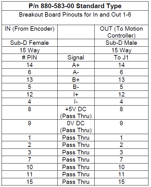
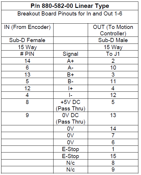
Out 1-6: DB-15 Male to Motion Controller. The Breakout board is programmable to accommodate different pinouts by the fabrication of special programming plugs. These are done at the factory for multiple repeat applications. For others, cable adapters are recommended. The standard pinouts are listed below.
In 1-6: DB-15, female from Encoders. The electronics are designed to accept RS-422 differential digital quadrature signaling. See notes above reprogramming plugs, and pinouts below.
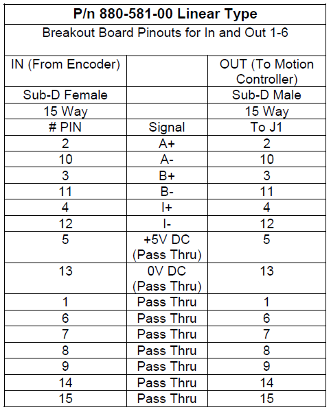
EIU I/O Pinouts
At this printing, we have three different programming plugs to offer. The DB-15 resulting pinouts are listed below. Different combinations of plugs can be used together, which can be useful in applications where there is a rotary stage system installed on a 3 axis linear system, each with different types of encoders. For manual systems, with no Motion Controller, the encoders can be powered directly from the EIU. Note that the A/B and Index pulse signals are buffered with RS- 422 receivers and drivers. All others are passed through.
Motion Requirements:
Predefined Moves – These are moves that will not be modified once a move has started. The stopping point is known before the move begins. They may be complex, in that they may be compound, and have a series of segments, with no stops between. For this type of motion directive, a low speed communication channel such as RS-232 is adequate, and response time of the controller need not be very fast. The user’s patience is the limiting factor, so typically a second would be tolerable. However, in applications involving production inspection, dwell time between moves and at start up can add up and must be considered.
Updates on the fly– These are moves where a move in progress may be modified in order to adjust a trajectory to track the surface of a part. In this mode of operation, the response time is more important than in predefined moving, but actual performance depends on the speed of travel. It would be reasonable to put a speed limit on moves in tracking mode, if response time could not provide an adequate safety factor. Also, it is important to build a software stay-out zone around the part before scanning in tracking mode to avoid collisions. The actual response time from the controller is only part of the story here. It is the full loop delay that matters. The loop include four steps: 1) The VP board generates a trigger pulse; 2) Encoder data is latched and passed to SSC; 3) SSC reads the probe data from the VP board, combines it with the encoder data and determines that a course correction is required; 4) The new course is passed to the CMM controller and executed. If tracking is being performed with an RPS 150 for example, with a field of view that is 40mm deep, and the part starts centered, and we assume that a correction is made when the part reaches the upper or lower 25% of the fov, that means it can move by 10mm before a correction is desired, and there is another 10mm of headroom before the part leaves the fov and is lost. If we assume that the part surface is sloped at 45° relative to the direction of travel, and that the move speed is 1in/sec, the loop delay can be no more than 10mm/1in/sec = .4sec. If we budget 50msec for position reporting, and another 50m sec to determine the new trajectory, that leaves 300msec to change to the new trajectory before loosing the part. Due to the relatively deep fov of the RPS probes, it is not necessary to follow an exact path. When a new trajectory is specified, necessarily there will be accelerations, which could get a little complex during a compound move if it were required that an exact path be followed, but it is not, so the default acceleration curves could be used, which lead to imperfect tracking. If the surface is still too near the edge of the fov of the probe, another correction could be made.
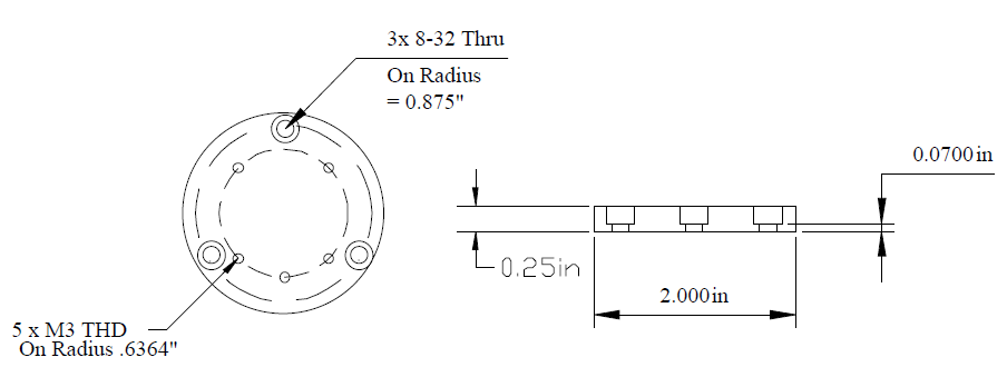
Probe Mechanical interface:
The laser probes are compatible with the Renishaw shanks, MS1 through MS17. The proper shank is dependent on the machine the probe is being used on. Additional mounts can be fabricated upon request. The adapter used to connect to the Renishaw shanks is shown below.
Native LDI Compensation Table Format Definition
Header: Axis XYZ x_step y_step z_step x_dim y_dim z_dim min_x min_y min_z
Step values are generally 1 inch
Dim value is the number of entries into the table for each azis. We usually add an inch on each end of the envelope so that all data is within the actual work volume. For example, a 3 inch axis would require a dim value of 6 (roundto the nearest integer and add 3).
Min values are the axis soft limits minus one, since we add one inch to the envelope in all directions.
Table:
XYZ in inches with Z values, increasing for each X, Y combination, and Y values increasing for each X. So, for a 3” square work envelope, the table would be as follows:
000
001
002
003
010
011
012
013
100
101
etc….