Executive Summary
It is often difficult to describe the accuracy of a 3D Laser Scanning system, because, to date, there is no unified standard that governs it. The typical scanning system from Laser Design is a CMM base with a laser line sensor attached in place of a touch probe. While determining the accuracy of the CMM base is simply a matter of running an ANSI B89 Ball Bar test using a touch probe, no such standard test exists for describing accuracy when a laser probe is attached.
In addition, Laser Design includes 4th axis automation, fixturing, and specific software solutions with its systems. These components may also impact accuracy, repeatability, and reproducibility. For a user who is scanning, for example, a cell phone housing for a first article inspection process, understanding how the system functions as whole is vital. For this reason Laser Design has defined a set of tests that will once and for all determine a machine’s performance. The tests are simple and are designed to stress the entire inspection process, from fixturing to data analysis.
Briefly, the tests include an adapted B89 test, using the Laser Sensor instead of a touch probe, as well as a Gage R&R Study using a certified, modified gage block.
Results
The tests described above were completed on a WS2030 machine base with an SLP 250 laser probe attached. Running the Adapted B89 test resulted in a machine accuracy of .00898 mm. This compares to results from a standard B89 test of .005 mm. The results of the Gage R&R test yielded a 5.15 sigma result of 0.0137 mm.
Background
A CMM based Laser Scanning system represents a complicated measurement tool, whose accuracy and repeatability can be difficult to gage, especially when you add a 4th axis and ball matching to the mix. In the past, system accuracy was estimated by simply adding the CMM machine accuracy to the stated laser probe accuracy. While this may get you in the ball park, it does not address all of the factors that can impact total system accuracy. For example, on a 3 axis system, you must also consider the alignment of the laser to the CMM base as a source of error. On a 4 axis system, the part sits on a rotary stage, which also must be aligned/calibrated before use. If you wish to scan both sides of a part, you may need to rely on ball matching to bring the data from each side back together. All of these factors can combine to impact system accuracy, repeatability, and reproducibility. In addition there may be error generated by the data analysis process. For example, it can be difficult to know the accuracy and repeatability of the software for registering the point cloud to its CAD model. If that isn’t accurate, any cross sections used for dimensioning may be in the wrong place.
Test
We have taken a two prong approach to try to solve these problems. First, we use a modified B89 ball bar test using the laser probe to identify 3‐axis machine accuracy. Because this test relies only on the laser for collecting data, it is a good measure of the impact of both laser accuracy and alignment of the laser on machine accuracy. By comparing this result to results collected from a standard B89 using a touch probe, we can quickly zero in on the error component introduced by the laser probe and its alignment.
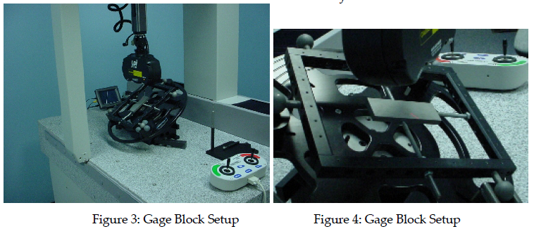
Second, we complete a Gage R&R test using a qualified modified gage block. We scan this gage block using standard practices – in this case we attach it to our Flip Fixture and scan using the rotary on both sides of the block. This provides data from use in real world conditions. We then bring the data into Raindrop Geomagic Qualify, which we recommend for inspection software. Because the gage block has been modified to include a hemisphere attached to its surface, it is now simple to accurately match the scan data to the CAD surface of the gage block created during the certification process. Without the hemisphere there was always the possibility that the scan data could match to the CAD in one of 4 ways. The hemisphere ensures that we compare the proper surfaces to one another. Finally, we take 6 measurements on the gage block and compare to the certified CAD. This test is repeated 3 times by 3 people to yield repeatability and reproducibility by the Average and Range method.
Adapted B89 Test
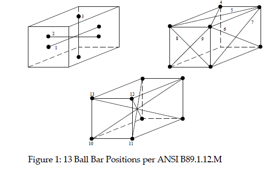
For our tests, we will perform a 13 position B89 test using an SLP 250 probe on a WS2030 machine base. The probe will be aligned using our standard methods (Probe Alignment Wizard) before each test. Surveyor Scan Control provides an Excel spreadsheet for calculating B89 test results. This will be used for determining the results of each test.
Materials:
- Ball Bar Kit with bead blasted test spheres – make sure the sphere diameters are known.
- LDI WS2030scanner – 3 axis
- SLP 250 laser probe
Setup:
- The setup procedure will be completed before each test.
- Probe will be mounted to the CMM using the PH10.
- Run the Probe Alignment Wizard.
- Silence any rotary stages.
Procedure:
- Open the ball bar template.ssc file from C:/LaserDesign/Surveor/Samples.
- Set up the ball bar in the machine work space for the position you want to scan.
- Select the layer that corresponds to the position of the ball bar.
- Open the Ball Scan Wizard (CTRL B), and move the laser over the 1st ball.
- Enter the proper sphere diameter into the wizard.
- Run the Wizard.
- When the system is done scanning, open the Ball Scan Wizard again. Make sure you have selected the proper layer first.
- Move to the second ball and finish the wizard.
- Repeat this process for each of the 13 ball positions required by the adapted B89 test.
- When complete, run Compute From Sphere Scans/Statistics on the root layer of the file.
- In the Goodness of Fit dialog, select Excel Export.
- Save the Excel file when it opens.
- Save the SSC file.
- Run this test 3 times for each probe.

Analysis:
- For each data set, open the Excel file that contains the Goodness of Fit data.
- Also open the Ball Bar Template.xls file.
- Copy the data from the data file into the template file on worksheet 2.
- Worksheet 1 will now calculate the ball bar results, which is the maximum range of ball bar lengths for each test.
- Save the Ball Bar results for each test.
- Compare the tests. Calculate an average and standard deviation for each probe data set (from the 3 test samples).
Setup:
- Each Operator must perform the setup procedure before completing the first measurement.
- Setup the WS machine for typical rotary scanning, setting up the rotary stage at 30 degrees from flat with the Flip Fixture attached.
- Run the Probe Alignment wizard to ensure proper probe alignment.
- Run the Rotary calibration wizard to ensure proper rotary calibration.
- Using the ¼ 20 rods and nuts, mount the gage block in the fixture frame. Use super glue to fix the block to the rods. Make sure that the block is firmly fixtured and does not move.
Gage R&R Test
For these tests, we use a standard Excel template that provides d(2) values for the R&R calculations, and sets up all required formulas. The template requires the test be run with no more than 10 measurements, 5 trials, and 3 people. The test must be run with a minimum of 2 samples each. In general, a test is set up to measure a part with the laser scanner. The part – a modified and certified gage block – is mounted in the fixture frame for scanning by the first operator. This operator then completes from 2 to 5 scans of the same part. The subsequent operators repeat the same number of trials after refixturing the part. Discrete measurements are set up in Qualify, and the parts are run through the Auto Report process to ensure repeatability in the measurement locations (relative to the CAD). The discrete measurements are then entered into the spreadsheet and R&R values can be calculated.
Materials:
•3” Gage Block, bead blasted and qualified on calibrated CMM
•CAD file representing the qualified gage block (IGES or STL surface)
•LDI WS2030 scanner – 4 axis
•SLP 250 Probe
•LDI Flip Fixture for 4th axis
•¼ 20 threaded fixture rod and nuts
•Super Glue January
Setup:
- Each Operator must perform the setup procedure before completing the first measurement.
- Setup the WS machine for typical rotary scanning, setting up the rotary stage at 30 degrees from flat with the Flip Fixture attached.
- Run the Probe Alignment wizard to ensure proper probe alignment.
- Run the Rotary calibration wizard to ensure proper rotary calibration.
- Using the ¼ 20 rods and nuts, mount the gage block in the fixture frame. Use super glue to fix the block to the rods. Make sure that the block is firmly fixtured and does not move.
Scanning:
- Attach the fixture frame to the Flip Fixture.
- Run the Ball Matching wizard to scan the balls for side
- Create a path plan for scanning the first side of the gage block. Scan the block using 0.010” spacing and at every 45 degrees on the rotary. Set the optimal exposure time.
- Save the path plan.
- Scan side 1.
- When side 1 is complete, flip the frame over to side 2.
- Run the Ball Matching wizard to scan the balls for side 2.
- Create a path plan for scanning the second side of the gage block. Scan the block using 0.010” spacing and at every 45 degrees on the rotary. Set the optimal exposure time.
- Save the path plan.
- Scan side 2.
- Complete the file by running the Ball Match wizard again. This will combine the side 1 and side 2 data.
- Save the resulting data layer as a .scn file.
- Repeat the steps above for the remaining trials for each operator. Each operator may use his saved path plans to scan subsequent trials, but they must make their own path plan for the first trial.
Analysis:
- Import the CAD model of the gage block into Geomagic Qualify.
- Set up Plane Datums on 3 perpendicular faces of the gage block model.
- Import the .scn file from the unpainted gage block.
- Remove all fixture data from the file.
- Run Select Outliers to make sure all fixture data is removed. Delete the selected outlier data.
- Run Auto Create Datums and Features. Qualify will find the Datums from the CAD on the point cloud automatically.
- Run Datum/Feature Align. Click the Auto button to automatically align the data to the CAD using the 3 datums.
- Run 3D compare to create an error map. Set the color map to go from +‐.0005 to +‐ .005 (inches).
- Create cross sections for dimensioning. Create 3 sections using the 3 cardinal system planes in the default locations.
- Create 2D dimensions on the 3 cross sections. Measure 6 separate dimensions.
- Create a report for the data.
- Once the report is created, you can automatically run the same report on the other 2 data sets. Replace the point cloud data (don’t forget to delete the fixture data). Then run the auto report function.
- When all reports are completed, use them to fill out the Gage R&R Template.
a) Enter the Nominal Measurement values into the Nominal Row at the top of the table.
b) Enter the numbers of parts, trials and operators.
c) Enter the part data into the proper columns and rows by trial product and operator.
d) The spreadsheet will calculate the results.
Results
Adapted B89 Test
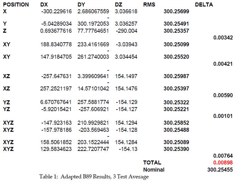
A 13 position Ball Bar test was run on the WS2030 scanner using an SLP 250 probe head. The test was repeated 3 times, after running the Probe Alignment Wizard between each test, to recalculate the Probe Alignment Matrix relative to the machine base. Table 1 below shows the test results, averaged over the 3 tests. The Total is the 3 test average of the maximum Ball Bar length range for each 13 position test. When a standard B89 test was run on this machine at installation, the results yielded an Average Test Delta of 0.005mm. The Adapted B89 test yielded an Average Test Delta of 0.00898mm.
Gage R&R Test
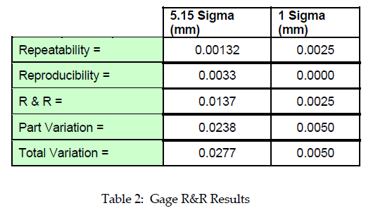
A modified gage block was scanned 3 times by 3 separate operators, and then compared to CAD model in Geomagic Qualify. The comparison process was automated so that the same measurement cross sections were used for finding dimensions on each part. These results were then tabulated in a Gage R&R worksheet, where various Gage R&R values were calculated. The results of the test are shown in Table 2. The 5.15 sigma column represents 99% confidence, while the 1 Sigma column represents roughly 67%.
Conclusions
At the start of this process, we were confronted with the problem of defining overall laser scanning system accuracy, repeatability, and reproducibility without any defined standard to lean on. We therefore developed a set of tests that would give us these results. We then applied these tests to a WS2030 laser scanner with an SLP 250 probe attached.
Running the Adapted B89 test was designed to show us the 3‐Axis machine accuracy when using the SLP 250 to collect data. Our results showed an accuracy of 0.00898mm, which compares to standard B89 results of 0.005mm for the same machine. When we take into account that the stated accuracy specification for an SLP 250 is 0.010mm, we can see that the original 3‐Axis accuracy assumption of adding the machine accuracy to the laser accuracy is a conservative assumption. This, in turn shows that using a ball bar to measure machine accuracy on a properly aligned machine will allow you to check the alignment of your machine without the need for a touch probe.
The Gage R&R test was designed to stress the typical scanning process. Therefore, the processes of fixturing, rotary scanning, ball matching, point cloud to CAD matching, and cross section measurement were tested together, while also allowing for operator variation. We found that at a 5.15 Sigma level – or 99% confidence – Repeatability was 0.0137mm, Reproducibility (operator variation) was 0.0033mm, and Part Variation was 0.0238”. The numbers, with exception of Part Variation, are all well within the assumed machine accuracy (touch probe B89 accuracy + laser accuracy, which should be about 0.015mm). The higher Part Accuracy number actually hinges on one specific measurement on all 9 tests. This indicates a variation between the CAD model and the actual gage block. This is not completely surprising, since the gage block CAD was built using 3 points on each surface to approximate the planes. Any surface variation in the part would not be included in the CAD model. This part error was also measured on a non calibrated surface of the original gage block, so it is not unreasonable to find that the surfaces are not completely flat. This also illustrates the capability of the laser scanner to identify differences between the CAD model and part repeatably.